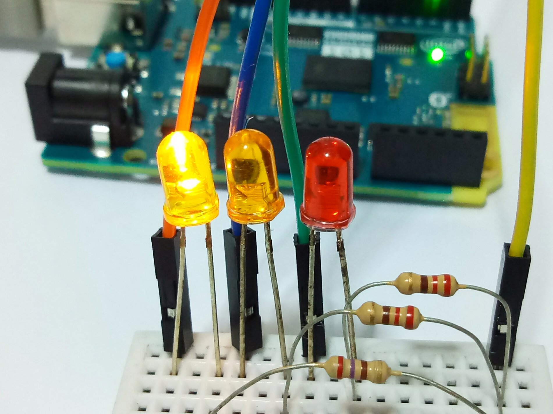

RobotControl Class RobotControl Description You can find examples for this library in the Examples from Libraries page. Ngi ta thng iu khin mc sng ti ca n LED hay hng quay ca ng c servo bng cch pht xung PWM nh th ny. Use it to make your own custom version of the Motor Board firmware analogWrite () l lnh xut ra t mt chn trn mch Arduino mt mc tn hiu analog (pht xung PWM). analogWrite() function generates PWM signal to Arduino's pin. Accordingly, We can use this function to turn on/off something such as: Turning on/off LED.

RobotControl: commands the Control Board as well as the I/Os and motors on the Motor Board, when running the default firmware. digitalWrite() function controls Arduino's pin to LOW or HIGH.There are two main classes that command the robot: int ledPin 15 // Analog pin 1 int temp //value place holder int vcc 255 // Set value to 5v equivalent int. Analog Blink This is an a wire connected from the Analog pin 1 to an led whose other pin is grounded. I modified the blink sketch and am trying to use the analog signals.
#ARDUINO ANALOGWRITE HOW TO#
The library exposes the sensors on both boards through a single object. I'm trying to to direct drive an 8x8 ledMatrix and I can't seem to figure out how to use the analog pins. However, it is recommended that novice programmers begin with programming the control board, leaving the motor board for later. It is possible to program both the Control and the Motor boards. Their functionality has been replicated inside the robot's library to optimize the code's size. It also relies on a number of Arduino libraries like TFT, SPI, and Wire. It relies on a number of 3rd party libraries including Fat16, EasyTransfer, Squawk, and IRRemote. This library enables easy access to the functionality of the Arduino Robot.
#ARDUINO ANALOGWRITE CODE#
This example code is in the public domain.This library is archived and is no longer being maintained. This example shows how to fade an LED on pin 9 Discuss the Sketchīelow is the sketch in its entirety from the Arduino IDE: /*

The button will turn orange and then blue when finished. The button will turn orange and then blue once finished. Plug the Arduino into your computer with the USB cable.Connect the long leg of the LED with the other leg of the resistor using an alligator clip.Take either leg of the resistor and place it in pin 9.Take the short leg of the LED and insert it in the GND pin. I experienced much confusion with analogWrite(), because I suspected that it had to do with the analog pins on the Arduino.By submitting this form you agree to the privacy policy, and can opt-out anytime. You will receive email correspondence about Arduino programming, electronics, and special offers.


 0 kommentar(er)
